Transformers: Definition and How They Work
Learn what an electrical transformer does, how magnetic induction transfers AC energy, and why grids step voltage up and down.
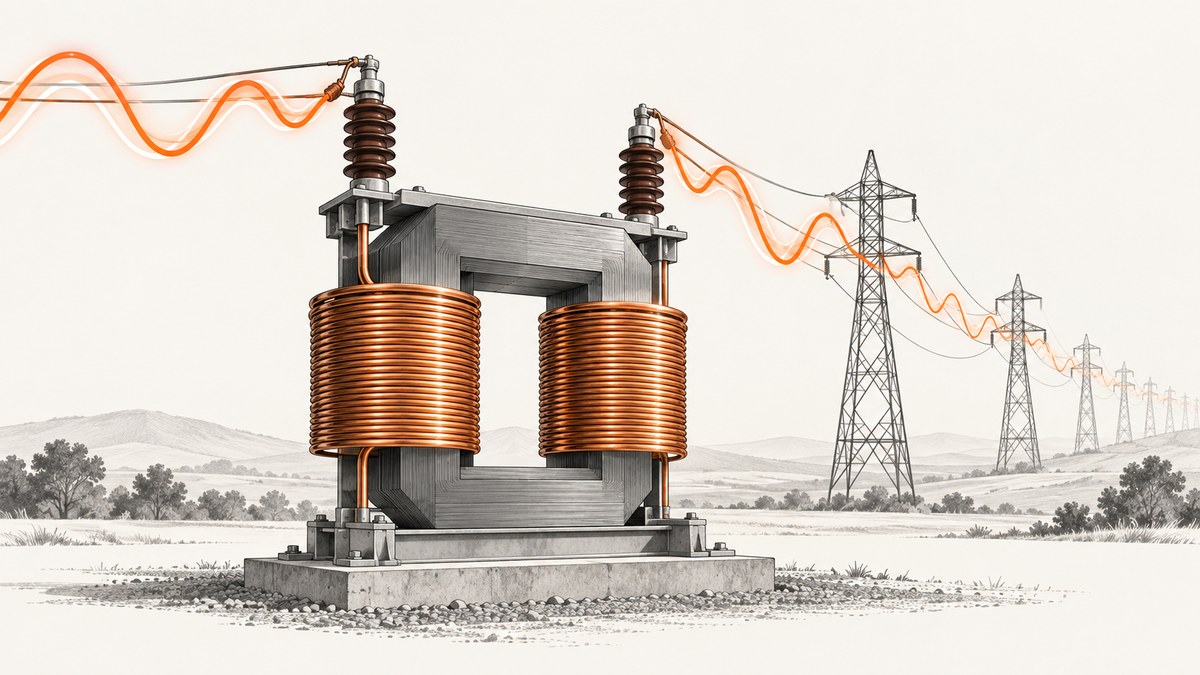
Short answer: An electrical transformer changes the voltage of alternating current (AC) through electromagnetic induction. AC enters the primary winding, creates a changing magnetic flux in the core, and that changing flux induces an AC voltage in the separate secondary winding. The number of turns on each winding determines whether the transformer steps voltage up or down.
Transformers do not create energy. In an ideal transformer, a higher output voltage is accompanied by a proportionally lower output current, so input and output power balance. Real transformers lose some energy as heat, magnetic loss and other inefficiencies. Their practical value is that they let the power system move electricity efficiently at high voltage, then reduce that voltage for delivery to homes and businesses.
What is a transformer?
The U.S. Energy Information Administration defines a transformer as an electrical device used to change the voltage of alternating current. A transformer normally has two insulated windings wrapped around, or coupled through, a magnetic core:
- Primary winding: the coil connected to the incoming AC source.
- Secondary winding: the coil connected to the load receiving the transformed voltage.
- Core: the magnetic path that links the changing flux from the primary to the secondary.
The windings are electrically separate. Energy crosses the separation through a changing magnetic field rather than through a direct wire connection. This is why a transformer can change voltage while maintaining isolation between circuits in designs intended for that purpose.
Transformers require changing current. A steady direct-current (DC) signal does not continuously change the magnetic flux, so it cannot produce the normal transformer action. AC naturally reverses direction and changes magnitude, providing the varying flux needed for induction.
How does a transformer work?
The operating sequence is easier to understand as a chain of causes:

- AC voltage drives alternating current through the primary winding.
- The primary current produces a magnetic field in the core.
- Because the current changes, the magnetic flux in the core changes continuously.
- The changing flux links the secondary winding.
- That changing flux induces an alternating voltage across the secondary terminals.
- If a load is connected, secondary current flows and power is delivered to it.
The U.S. Department of Energy describes this as energy transfer by magnetic induction between coils through varying magnetic flux. The core concentrates and guides the flux so that as much of it as possible links both windings. The primary and secondary do not need a metallic connection for this transfer to occur.
The turns ratio
For an ideal transformer, the voltage ratio follows the turns ratio:
Vsecondary / Vprimary = Nsecondary / NprimaryNprimary and Nsecondary are the numbers of turns in the two windings. If the secondary has twice as many turns as the primary, its voltage is approximately twice the primary voltage. If it has half as many turns, its voltage is approximately half.
Current changes in the opposite direction in the ideal model:
Isecondary / Iprimary = Nprimary / NsecondaryCombining the two relationships gives the ideal power relationship:
Vprimary × Iprimary = Vsecondary × IsecondaryThese are engineering relationships for the ideal model, not a promise that a physical unit has zero loss.
Step-up and step-down transformers
| Type | Secondary turns | Output voltage | Typical grid role |
|---|---|---|---|
| Step-up | More than the primary | Higher than the input | Raises generator voltage before long-distance transmission |
| Step-down | Fewer than the primary | Lower than the input | Lowers transmission voltage for communities, buildings and equipment |
A step-up transformer does not add power. In an ideal case, raising voltage reduces current by the same power ratio. A step-down transformer performs the reverse conversion: lower voltage with higher current for the same ideal power transfer.
Why do power lines use transformers?
Power lines have resistance. Current flowing through that resistance produces resistive losses. For a given amount of transmitted power, increasing voltage allows the system to carry less current. Lower current reduces those line losses, which is why grids transmit electricity at high voltage over long distances.
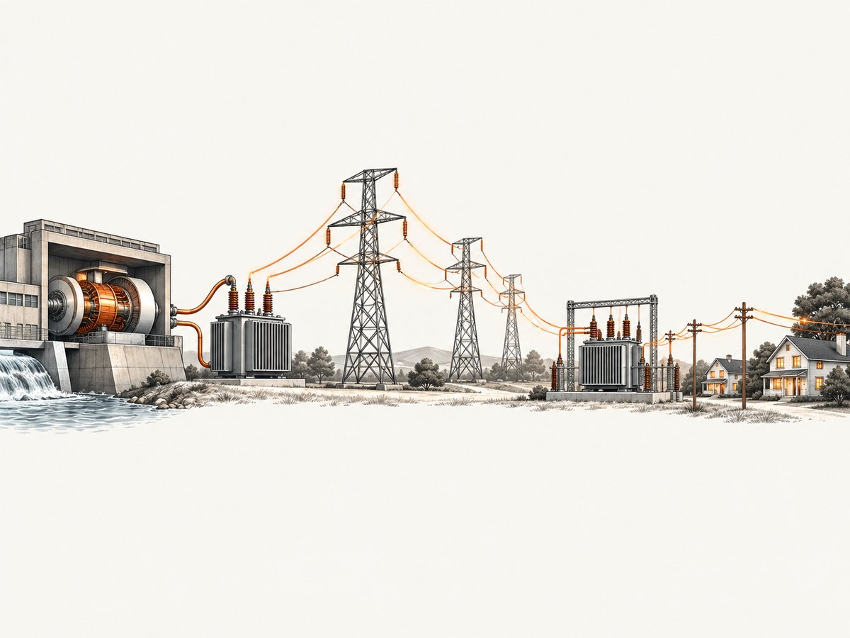
The grid therefore uses transformers at several points:
- Generation: electricity leaves a generating plant and passes through a step-up transformer.
- Transmission: high voltage carries power across long distances with lower current than would be required at the original generator voltage.
- Substations: transformers reduce the voltage in stages as power approaches populated areas.
- Distribution: local equipment lowers voltage again for delivery to homes and businesses.
The Department of Energy gives wind plants as a concrete example: a step-up transformer raises voltage, reducing current and decreasing long-distance transmission losses. Substations then lower voltage for consumers. The EIA similarly explains that transformers raise and reduce voltage as electricity travels from power plants to homes and businesses.
Ideal transformers versus real transformers
The ideal transformer is a useful model. It assumes all magnetic flux links both windings, the windings have no resistance, the core has no magnetic loss, and input power equals output power. Real hardware violates each assumption to some degree.
Real losses include:
- Winding resistance: current heats the wire and dissipates power.
- Core losses: the changing magnetic field causes losses in the core material.
- Leakage flux: some magnetic flux does not link both windings.
- Auxiliary losses: physical construction and operating conditions introduce additional losses.
Transformer efficiency is defined as output power divided by input power:
efficiency = output power / input powerEfficiency is below 100 percent for a real transformer. The voltage ratio can still be close to the turns ratio while the delivered power is lower than the input power because some energy becomes heat or other losses. A voltage increase is therefore not free energy.
What happens under load?
With the secondary open, the transformer develops a secondary voltage but supplies little secondary current. When a load is connected, secondary current creates its own magnetic effect. The primary draws additional current from the AC source so that the core flux remains consistent with the applied voltage and frequency. In the ideal picture, the source supplies the load’s required power; in a real unit, it supplies that power plus losses.
This explains why a transformer can be rated for a particular load even though its no-load voltage and loaded voltage are not exactly identical. The turns ratio describes the basic conversion, while winding resistance, leakage flux and the load affect actual terminal voltage.
Common questions about transformer behavior
Can a transformer change DC voltage?
Not by ordinary transformer action. The induction mechanism needs changing magnetic flux, which a constant DC current does not provide. Power electronics can first switch or convert DC into a changing waveform, use magnetic components, and then rectify or regulate the result, but that is a larger conversion system.
Are the primary and secondary connected?
In a conventional transformer, the windings are separate conductors. Magnetic coupling transfers energy between them. Some specialized arrangements share winding sections, but that is outside this basic explanation.
Does a step-up transformer increase current too?
No. In the ideal relationship, higher voltage corresponds to lower current for the same power. Real losses mean the output power is slightly lower than the input power.
Why use AC in the grid?
AC can be transformed to different voltage levels with magnetic induction. That makes it practical to raise voltage for transmission and reduce it near consumers, as described by the DOE and EIA sources.
A small browser demonstration
You can visualize the sequence without connecting to live electrical equipment. The following self-contained page animates alternating current in the primary, changing flux in a core, and an induced waveform in the secondary. It is a conceptual visualization, not a circuit simulator or a construction guide.
<!doctype html>
<canvas id="c" width="900" height="360"></canvas>
<script>
const ctx = document.querySelector('#c').getContext('2d');
let t = 0;
function wave(x, y, amp, period, phase = 0) {
  ctx.beginPath();
  for (let i = 0; i < 360; i++) {
    const px = x + i * 1.35;
    const py = y - amp * Math.sin((i / period) + t + phase);
    i ? ctx.lineTo(px, py) : ctx.moveTo(px, py);
  }
  ctx.stroke();
}
function draw() {
  ctx.clearRect(0, 0, 900, 360);
  ctx.strokeStyle = '#222'; ctx.lineWidth = 3;
  ctx.strokeRect(385, 70, 130, 220);
  ctx.strokeStyle = '#1769aa';
  wave(20, 125, 45, 24);
  ctx.strokeStyle = '#c44';
  wave(520, 235, 25, 24);
  ctx.fillStyle = '#222'; ctx.font = '16px sans-serif';
  ctx.fillText('primary AC', 20, 55);
  ctx.fillText('changing magnetic flux', 360, 325);
  ctx.fillText('induced secondary AC', 520, 55);
  t += 0.08; requestAnimationFrame(draw);
}
draw();
</script>
The left waveform represents the alternating primary input. The center block represents the magnetic path, and the right waveform represents the induced secondary voltage. Changing the number of turns in a physical transformer changes the voltage ratio; changing the animation amplitude only changes the drawing.
Or skip the browser setup
If you are documenting transformer diagrams, grid flows or any other web page and need a clean image, ScreenshotNeo can capture it with one request. Its API accepts a URL and returns PNG, JPEG, WebP or PDF output. Cookie and consent banners, newsletter popups and chat widgets are removed before capture. Bot checks, blank pages, timeouts, failed loads and cache hits are not billed, and the response identifies the page verdict and billing status.
Use the same call from the ScreenshotNeo API documentation:
curl -G "https://api.screenshotneo.com/v1/shot" -d access_key=YOUR_API_KEY --data-urlencode url=https://stripe.com -o shot.webpimport requests
r = requests.get("https://api.screenshotneo.com/v1/shot", params={"access_key": "YOUR_API_KEY", "url": "https://stripe.com"}, timeout=90)
open("shot.webp", "wb").write(r.content)const q = new URLSearchParams({ access_key: 'YOUR_API_KEY', url: 'https://stripe.com' });
const res = await fetch(`https://api.screenshotneo.com/v1/shot?${q}`);The service also provides an MCP server for AI agents, including Claude and Cursor, with tools for screenshots, page information and PDF capture. You can use 1,000 screenshots per month free with no card; paid plans start at $5 for 3,000 shots. Create a free ScreenshotNeo account.
Troubleshooting the concepts
| Observation | Likely cause | What it means |
|---|---|---|
| No induced secondary voltage | No changing primary current or no magnetic coupling | Induction requires changing flux linking the secondary. |
| Output voltage is lower than the simple turns calculation | Winding resistance, leakage flux or loading | The ideal ratio is an approximation for real hardware. |
| Voltage rises but available current falls | Normal power relationship | A step-up conversion trades current for voltage. |
| Input power exceeds output power | Real transformer losses | Efficiency is output power divided by input power. |
| Transmission still loses energy at high voltage | Line resistance and other system losses remain | Transformers reduce current-related losses; they do not eliminate every loss. |
Performance, reliability and cost considerations
For a grid system, the useful performance question is whether the selected voltage levels reduce transmission losses while delivering the required voltage downstream. Efficiency, thermal behavior, winding resistance, magnetic coupling and load conditions all affect the result. A transformer can be reliable while still having measurable losses; reliability and efficiency are related but distinct engineering properties.
For documentation and demonstrations, a screenshot workflow has different concerns. A local browser script gives maximum control but requires a browser runtime, page loading, timing and cleanup of overlays. ScreenshotNeo moves that setup to an API call. Its options include full-page capture with lazy images loaded, CSS-selector element capture, custom CSS and JavaScript, click and wait actions, request blocking, headers and cookies, device presets, retina scale, PDF settings, caching with a chosen TTL, asynchronous jobs with signed webhooks, bulk capture for up to 100 URLs per call, signed public image links and a usage API. Every feature is available on every plan.
FAQ
What is the one-sentence definition?
A transformer is an electrical device that changes AC voltage through electromagnetic induction between separate windings.
Where does the voltage ratio come from?
In the ideal model, secondary-to-primary voltage equals secondary-to-primary turns.
Why are transformers placed near substations?
They reduce transmission voltage in stages before electricity reaches consumers.
Does a transformer improve total energy efficiency?
It enables high-voltage transmission with lower current and therefore lower line losses, but the transformer itself has losses and is not perfectly efficient.
What should a beginner remember?
AC creates changing flux; changing flux induces secondary voltage; turns determine the voltage ratio; and real losses mean output power is lower than input power.
Sources
- U.S. Energy Information Administration glossary, transformer definition.
- U.S. Department of Energy Electrical Science handbook, magnetic induction, windings, turns ratio and efficiency fundamentals.
- U.S. Department of Energy, Explore a Wind Turbine, step-up transformers and transmission losses.
- U.S. Department of Energy, Electricity 101, high-voltage transmission.